Gain and binning gain & e-/adu

I am new to using a cmos camera that the gain and offset can be controlled.

In the equipment manager there are some fields for Gain e-/adu of the camera for different binning levels.

How does one figure out what values to be put in these fields. Are they even really relevant?

Also is it really efficient to bin CMOS cameras? Reason I am asking is my as/pixel scale is really small and thought maybe binning might help with that some.

Oh it is an ASI1600mc pro OSC.

Thanks.

1 Like

Funny you should ask. I have the same camera and the same questionsā€¦
Much interest in an answer.

Grain of salt because Iā€™m still learning but here is what I have gathered so far as a 1600mm ownerā€¦

The Binning is Software binning not hardware binning, the only ā€œbenefitā€ is that the file size being downloaded will decrease. So if you find your download times to be long or want to increase the speed of focusing or plate solving you can use the bin settings on those functions. In my personal experience it has not been a big gain in time so I just use 1x1 for everything now.

As to the e-adu numbers, I have never really had any success with getting an optimal exposure time to generate no matter how many times I mess with those settings. So I gave up on that.

IMHO your main concerns with the cmos camera is the gain and offset settings (currently only controlled via the ASCOM driver settings, but I have seen some discussions that this will eventually be supported by SGP). Iā€™m a fan of ZWOā€™s default settings labeled ā€œunity gainā€ and ā€œHighest dynamic rangeā€. Off the top of my head these are gain 139 and gain zero settings.

I use gain zero when I travel to dark sites with no moon. I use 139 when Iā€™m doing stuff at home in my driveway.

Not sure if thatā€™s the best but hope this helps you out. Again still learning myself so I might have something backwards or totally wrong.

From what I understand you should ā€˜neverā€™ use a 0 offset it will clip things.

Unity is 139 offset 20 from the discussions I have read.

What I was wondering was to enter in SGP for the binning and gain settings. I guess that even if you do bin an image the gain remains whatever the camera is set to at the time for ā€˜unityā€™ it would be 1?

1 Like

Highest dynamic range is Gain Zero and Offset 10 Unity is Gain 139 and offset 21

As far as I know SGP is not yet controlling those at the camera level. I had seen some discussion about them going to or trying to support this but as far as I am away you have to control those via the driver software. And if you are using the ASCOM connection you have to control via the driver only.

As to the read noise according to the chart published by ZWO itā€™s 5 e-ADU for the highest dynamic range setting (again gain zero offset 10) and itā€™s 1 e-ADU for Unity Gain setting (gain 139 offset 21).

Remember ā€œhighest dynamic rangeā€ and ā€œunity gainā€ are just labels for the settings behind them. I could name them Bert and Ernie if I wanted.

1 Like

Iā€™m very new to this ,Iā€™v seen lots of advice saying ā€œyou control the gain on the driverā€ .What is the procedure to do it?.Any step by step instructions would be really helpful. Thankā€™s.

Let me try from memory and a little later today Iā€™ll fire up my laptop and lookā€¦

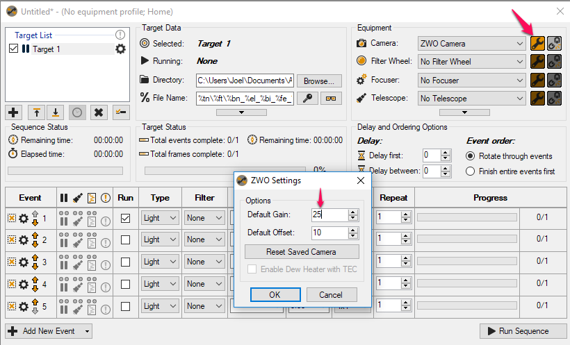
From memory: You can get to this in a couple of different places the easiest is probably when looking at the sequencer window there is a wrench icon next to each piece of equipment. When you click the wrench on the camera the driver setttings box gets displayed. Here is where it gets interesting. If you have the very latest ZWO drivers only the gain setting is exposed. There is a slider and box to type the number. There is also an advanced button that will unlock the offset and USB setting sliders. Also contained in the box is a drop down box for the 3 pre-defined settings we have been talking about here.

If you have the older ZWO drivers then all these things are exposed without having to hit the advanced button.

So prior to using the ā€œconnect all equipmentā€ menu, Iā€™d click the wrench and make sure the driver is set to what I want.

I find many of the descriptions of gain and offset in this forum and in Cloudy Nights a little confusing. The software configures the hardware so I have analysed the hardware in an attempt to work out from first principles what the settings do for us and how it affects the quality of our image. I apologise for this being long, but there is a lot to describe.

Each time a photon hits the imaging chip there is a chance (the quantum efficiency) it will be captured and generate a free electron that will then become trapped in the insulated gate of the CMOS image cell (pixel). The pixel is one plate of a capacitor that is charging up one electron at a time as the light is received. When the image is read, the voltage on each gate is amplified via the programmable gain amplifier (PGA) that sits between the cell and the digitizer (analog to digital converter). The resulting voltage is converted to a 12 bit digital signal (our ADUā€™s).

              Image cell (capacitor)  ->  PGA  ->  12 bit Analog to Digital Converter -> the image

The voltage on a capacitor is proportional to the number of electrons and the size of the capacitor plate. In this chip the voltage generated by 20k electrons is the voltage Panasonic calibrated the internal reference voltage so that the digitiser output is a full reading of 4095 (65535 in SGP as it scales it). Since the PGA can be set to any value from 0 to 300 where each value corresponds to a 0.1dB step in the gain, we have 300 different gains available to us that correspond to a scaling of the voltage from 1 to 25.5 (you can set the Gain value to more that 300, but the chip itself is configured so that 300 is the highest value). So, if we are scaling up the voltage by 25.5, then full voltage out of the PGA is achieved with 1/25.5 of the voltage going into it from the image cell. This is the voltage that would be achieved by 20,000/25.5 = 785 electrons (you can see this on the graph published by ZWO). Similarly, a gain of 139 corresponds to a voltage gain of 5.002 and therefore full digital signal is achieved with a well containing 4,000 electrons. If we change the starting point from a nominally advertised 20k electrons to exactly 20,485 electrons it will generate enough voltage to give full signal after the amplifier with 20,485/5.002=4095 electrons. Huh!, this is exactly 1 electron per digital count (ADU) just like they advertise.

If we set the gain to 85 then 8185 electrons are needed to read a full 12-bit signal of 4095. Every second electron makes no change to the signal we read (quantisation error or noise), but we can see a greater range of brightness because we can see from dark to twice as many photons and everything in between. Put another way, the noise has gone up because of the steps in signal and sometimes no step when we have more signal, but the dynamic range is greater because we can collect more electrons before we saturate the digitiser. Low brightness regions will have fewer steps in the brightness, so a stretched image could look banded rather than a smooth graduation in intensity, but the bright stars will look great.

If we set the gain to 215 then 2034 electrons will lead to a full 12-bit signal. This means that every half electron will lead to one more bit increase in the reading. It sounds great, but we canā€™t have half an electron, so the digitised signal is going to step up two counts each time an extra electron is captured by the sensor. This will show up as increased noise and lower dynamic range. We could have done this by stretching the resulting image.

In summary, any gain greater than 139 will lead you to a risk that the lower dynamic range will limit the quality of your image. A gain of less than 139 will give you higher quantisation noise, but the benefit of higher dynamic range, stars that arenā€™t blown, but any weak nebulous regions will have fewer steps in brightness available. In my opinion the electronics is geared up so that 139 is the correct setting and the only time it is worth using a different value is when you must have a higher dynamic range for an object without nebulosity, such as with a globular cluster. The Offset is an outcome of the amplifier gain on internal leakage currents that offset the voltage, so we should follow the manufacturers recommended value to do what they have measured is needed.
Please note that this is an analysis of the electronics, not of astrophotography. The electronics is easier.

1 Like

First of all thanks for that break down Generator, it is quite informative and helps me to understand just what is going on when we adjust these numbers. Helps to make sense of it all.

As to the ā€˜controlā€™ it is my understanding as of right now to choose the ā€˜ZWOā€™ camera from the list of cameras and to set the gain and offset for the ā€˜defaultā€™ of 139 / 21.

Then the gain and offset can be controlled within the sequence per event level by clicking the gear icon next to each event. Not in front of the imaging computer right now so I donā€™t know the full names and specifics but within the ā€˜gearā€™ icon there is a dialog box than can be filled in with a gain and offset for each event of the target.

What I donā€™t fully understand is if the values placed in the per event fields are actually controlling the camera, or are just numbers that can be placed in the file name and the camera actually uses what you set as a default.

I have only had one chance to use this camera since I got it (excluding flats and darks) so I donā€™t have a full understanding of the ā€˜mechanicsā€™ of control.

I am not sure 100% but I donā€™t think you can control gain and offset yet via SGP directly like that. I believe that as I said before you must set those via the driver. I know that the team has been working to support that inside SGP but I have not seen a ā€œyes/noā€ on it working or not yet.

Gen thatā€™s one of the best hardware breakdowns Iā€™ve read so far. Excellent stuff

rottielover, you can control both gain and offset if you use the native ZWO driver (not ascom driver). As UlteriorModem describes, those settings are found by clicking the gear icon in each event (ā€œEvent Settingsā€).

Excellent. Thank you, I will try this out as soon as the clouds clear again :wink:

I just ran a quick test cause I am bored and it is raining out.

With the camera on the bench I made a brief test sequence with two events, a uni gain and a hi gain.

Using the ZWO driver I set the gain and offset per event, event 1= 139 - 20 event 2= 200 - 60

I can report that indeed the camera gain and offset is indeed controlled via the per event setting. This is good news!

1 Like

Thank you very much Generator, excellent explanation.

Thanks SdA. It was interesting trying to get the information from Panasonic. They seem to have a business model that includes only releasing technical data sheets to manufacturers like ZWO. It was made more difficult by the fact that ZWO ordered the chips with some customisation to suit the use in an astrophotography camera. It also helped that I have had clouds and rain for five weeks straight.

Thankā€™s for the info .I will have a go.

Iā€™m trying this out tonight. I found the settings, but when I create a new event by clicking the arrow and clicking ā€œcopy event 1ā€, the Gain and Offset settings are not copied over to the new even and I have to set them for each eventā€¦ ? Or will that just carry over when they are left at ā€œnot setā€?

I just tried to copy an event, and as you say the gain and offset settings are not carried over. So you definitely need to change those settings manually. Do NOT leave it as ā€œnot setā€.

I ā€˜thinkā€™ that if it is left as ā€œnot setā€ the camera will use the same gain and offset as the previous event.

I have not actually tried this but that is what I understand.

This is not correct. If the settings are left ā€œnot setā€ then it will use whatever gain and offset are defined in the driver itself.