Dome Alignment

Hello all,

I have been out of things for nearly two years due to building an observatory with dome and associated driver software using the ASCOM Dome template. I am field testing the dome at present and in general it seems to work well in tests with POTH so last night I tested with SGP and obtained slightly different results.

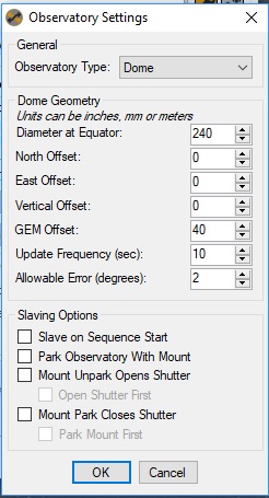
I have described below the process I followed and pasted in a screenshot of my dome settings, also link to log file.

The equipment I use is:
Celestron C11
Sitech Controller with MESU 200 Mount
PHD2 latest version
SBIG camera
SGP

Process
set up an LRGB sequence for NGC4565
Connect the equipment including the Dome, but slave Dome not checked at this point
Align the dome slit with the scope (by looking from behind scope)
Blind solve to sync the mount
Slew to target (NGC4565)
Manually align the dome slit once more
Centre now
Start PHD2 guiding
At this point I am ready to start the sequence, so I noted the telescope azimuth, which is provided by the Sitech controller interface and set my Dome encoder (reads in degrees from 0 to 360) to be the same as the scope azimuth, this value was 210 degrees.
In the SGP control panel, I ticked ‘Slave to telescope’
So at this point, in my head, I’ve got everything aligned, one more look from behind the scope to see that it is aligned with the dome slit and then I started the sequence.

The dome stepper motor MCU then received a request for a move to Azimuth 189 and moved the dome there. So at this point, the scope is looking at azimuth 210 and the dome has moved to Azimuth 189.

In order to continue and check if the dome would track the scope, I temporarily held the encoder at 189 and realigned the dome slit so that the scope and slit were aligned. There was some fiddling then to get guiding restarted, the good news is that the dome driver software received and responded to SGP’s Azimuth requests. At the end of the session, the Sitech controller was reporting the scope azimuth as 239 and the last request the dome driver received was for a move to Az 227 degrees giving a 12 degree lag of the dome behind the scope.

Please excuse if I have some minor discrepancy here as I’ve written from memory and notes taken at the time. I’m sure the log file will have the facts.

I am new to domes and dome drivers, so any help much appreciated, I’ve probably set a value incorrectly in SGP’s dome settings.

Here is the SGP dome dialog:

Obs

and here’s a link to the log file.

https://drive.google.com/open?id=1HSWSX-Ljje8X6X7RpdOajGAXUse6kdyD

Many thanks for your help,
Paul

1 Like

My apoplogies that I have just seen the observatory docking module which reports dome azimuth. I will try again and this time use the sync button. I’ll report back.

thanks
Paul

A couple of questions to help understand what is going on. Firstly, you said you tested with POTH and then with SGP. When running with SGP are you still using POTH? For example, in my setup I connect both my mount (CGX-L) and my dome (Pulsar with home-made ASCOM driver) to POTH and then select POTH rather than Celestron as my Telescope driver in SGP. In this configuration I select Slave Dome in POTH, not in SGP. Second, I presume you are aware that with a GEM mount the only instance where the Dome Azimuth and the Mount Azimuth will read the same is when you are aligned with Polaris (assuming you are in the northern hemisphere). At all other times the dome Azimuth will lag or lead the mount Azimuth so ensuring the telescope is centred in the dome slot as the mount lays east or west of the pier. A final point, I have update frequency set to 1 minute and allowable error set to 1 degree and this works fine with a 60cm slot width and a C14. I think you are updating too frequently, but that only causes unnecessary wear on the mechanical stuff and otherwise isn’t a problem if you want to keep it at 10s.

Thank you for helping with this. In previous tests, I used Cartes du Ciel with POTH and used POTH’s connect buttons to connect to a .net scope simulator and my dome driver. It was a week or so ago, but I’m sure that when I ticked slave dome in POTH, the az reported on the right hand side of POTH’s interface was the same as that reported on the left. I assumed the left side az was scope and rhs was dome az. The fact that these two were the same after slews/ whilst tracking, gave me some confidence that things were right, however I appreciate what you’ve said about GEM geometry. I’ll try again with POTH and this time let it move the dome so that I can physically check that the scope aligns with the slit.

When I tried with SGP I did not use POTH, just used the sequencer’s connect buttons to connect directly to my ASCOM dome. When the dome was requested to move to 189, that was way out of alignment. - SGP had centred correctly as a 3 minute capture got me an image of NGC4565.

I think I need to do more tests to establish if POTH connection works differently from a direct SGP connection.

I guess I could test during daylight if I used a planetarium, it would be approximate in terms of syncing the scope, but probably accurate enough for me to stand behind the scope and check scope-slit alignment.

Thanks for your comments, it’s got me thinking around things which is good.

I agree with you on frequency of update!
Paul

The red light for me was when you said that you read the azimuth from the scope and set the dome to that. That wll not set the dome azimuth to what is required to allow the scope to see out because of the GEM offset.

I’m not sure of a way to set the dome azimuth from the scope azimuth for a GEM, really I think you need an independent way to set the dome azimuth, such as a home sensor that the set the dome azimuth to a known value.

Paul, you can certainly test in daylight. Power-up your mount and park it on Polaris if that’s not your normal park position. Connect your mount to POTH (scope-dome hub) and you should see an Az reading of approximately zero degrees. Make sure you have input your dome geometry settings into POTH. Manually rotate your dome to zero degrees and connect your dome to POTH. You should now see a shutter azimuth reading 000.00 and very close to the mount reading. Select Slave Dome in POTH. Now slew your mount anywhere in the sky. Your dome should begin to slew also (mine is much slower than my mount slew), but when the dome stops moving you should be able to ‘eyeball’ the scope and if all is set up correctly, you should be looking directly through the middle of the slit. As you slew the scope to different locations you will see greater/lesser divergence between the scope AZ reading and the Dome AZ reading, but always the eyeball should be in the centre of the slit. If that works then all you need when darkness descends is to power up SGP, connect Telescope (and Observatory) to POTH Hub. If you are using PHD2 don’t connect this to POTH but to your regular Telescope driver.

Thanks very much for replies. I’ll try this out and report back.

Just one related question then, when setting up for an evening’s imaging, presumably its unpark which initialises the scope and Dome so that they are synchronised? I don’t use a pointing model currently, just blind solve to sync the scope to the sky, then use SGP to centre on the target. So I guess my modified workflow would be to a) do as you’ve suggested to sync the scope and dome, b) Set park, c) Park

Switch off the electronics, come back at some clear night in the future, unpark, blind solve to sync the scope to the sky, then centre on a target, run sequence etc. Does that sound right?

thanks,
Paul

To amplify what Buggs says about the start position, you need to have the Dec axis counterweight shaft pointing directly down so the scope is directly above the mount. This will ensure that the GEM offset doesn’t matter when you set the dome so the scope an see out.

The Telescope Unpark command makes the telescoper eady to operate but does nothing to the dome. I don’t know if SGP does more, or if it makes any attempt to initialise the dome position.

Domes can set the start position using the FindHome command, this should cause the dome to move to an index position and set the dome azimuth to that position. It must be implemented in your dome driver. An alternative, also in your dome driver, to have a way to determine the dome azimuth directly.

When I implemented dome control I used a digital compass module connected to the dome to detect the magnetic azimuth and the driver used that to determine the dome azimuth. It needs code to convert from magnetic to true azimuth but that’s just software.

Paul, the response from Chris looks good and is particularly relevant if you are looking for full automation utilising dome encoders of some sort. My system is (presently) simpler in that I haven’t set up the encoders BUT, possibly in your case (and certainly in mine) much depends on how your mount and dome drivers (and your dome motor control) function when powered-down at the end of a session, and then when first booted-up at the start of a new session. Much also depends on where your mount and dome rest at the end of a session, and what, if any storage exists for the at-rest positions. Assuming you have confirmed that, once running, your dome and scope positions are synced (ie the eyeball test works at all scope positions), then the critical thing when starting a new session is to be sure that the dome is physically, and electronically synced to the mount Az position before you slew to your first target. How you achieve this (your start-up work flow) depends on the foregoing BUTs. In my case I don’t use dome encoders so when I power up my dome driver and associated stepper control (which are running on an Arduino Mega 2560) and then connect the dome driver to POTH my dome azimuth position reads 000.00 regardless of where the dome is actually pointing. Usually, at the end of an imaging session my last action before shutting down is to park the mount and the dome (which leaves the scope pointing at the celestial north pole and the dome slot facing due north). Provided I haven’t manually moved the dome before the next imaging session then on power-up the dome azimuth of 000.00 will be correctly synced with the mount. If I have moved the dome then I must remember to manually return it to due north before power up. So my start-up work flow is to power everything up (POTH, SGP with chosen target, dome Arduino), initialise the mount finishing with ‘quick align’ (which leaves the scope pointing at the CNP), connect everything in SGP (at this point I can see POTH showing the scope azimuth reading approximately zero degrees and the dome showing 000.00 degrees) and the ‘slave dome’ in POTH is ticked. When I run the sequence the first action is to slew to target (moving the mount and the dome to the approximate location), then to centre and sync (which gets the mount to a few arc-seconds with the dome following if necessary). Good luck.

Thanks very much for this Chris and Buggs - very helpful, I’ll experiment a bit and feel sure I’ll sort it out now.

all the best,

Paul

Hi again,

I noticed today that my pier is not quite central in the dome, so I will need to put some figures in the poth setup. I looked at the poth help file, but the link to the geometry explanation in the ASCOM help file page is broken.

My pier to dome periphery measurements in mm are as follows:

Pier to north dome edge 930
pier to south dome edge 1010

pier to west dome edge 930
pier to east dome edge 980

I guess that these differences will affect the dome AZ calculations, so I need to enter them into POTH

Unfortunately, I don’t understand what poth needs, so given the above numbers, can you let me know what to enter into the POTh fields?

Another question is where to measure the above figures from? Is it the intersection of RA and DEC axes?

Many thanks for help,

Paul

The mount offsets are all measured from the centre of the circular dome to the intersection of the Ra and Dec axes on the mount. The units don’t matter as long as you use the same ones for everything, all mm, all cm, all inches.

The pier position isn’t the same as the intersection of the Ra and Dec axes so you will probably need to re measure but from what you post the NS dimension of your dome is 930 + 1010 = 1940 and the EW dimension is 930 + 980 = 1910. The NS offset is (1010 - 930)/2 = 40mm North and the EW offset (980 - 930)/2 = 25mm West.

Given a dome of that size these are pretty small offsets and won’t have a large effect, something like 2 degrees, the GEM offset is the major contributor to the difference between the dome and scope azimuth.

Paul, in the POTH Setup ‘Geometry’ section you need to enter the various measurements (you might find this helpful http://www.scopedome.com/en/ScopeDomeDriverHelp/geometria_kopuly.htm). Be careful in that all measurements should be in mm EXCEPT Dome Radius which is in metres.
All measurements are made from an imaginary point at the intersection of RA and DEC axis on your mount. This will be inside the body but make an estimate of its position.
The GEM Axis Offset is the distance between the intersection and the optical axis of your telescope. Don’t forget that a top mounted guide scope will significantly increase this distance.

thanks again for help, I’ll plug the figures in and see how it goes.
Paul

Hello again Chris and Buggs,

I have tried 6 tests based on the info you have provided and there is good news and bad (as always!)

Here’s my process.

Manually move the mount counterweight down and the scope looking at CNP both directions checked with a spirit level.

Move the dome slit to align with scope and set the angle encoder to 0 degrees

Start the scope controller (Sitech) and align the mount with polaris (select polaris from list and click sync).
Reset Arduinos (they are programmed to establish comms and if this is successful they display a message on an LCD)

start POTH
connect scope - POTH reports Azimuth 359
Connect Dome - POTH reports Azimuth 0 degrees

Click Slave Dome - and this is where it seems to go wrong. POTH requests a slew to azimuth 343 and the dome driver sends that to the stepper motor and away it goes to Az 343.

From this point, I have slewed the scope with the handset and the dome does track it, but most destinations i go to (looking mainly south to west with scope on E side of pier) leave the dome pointing about 35 degrees too far to the west.

Here’s what I have in POTH setup geometry
scope position +E/-W -40 (mm)
Scope Position +N/ -S 0 (I re measured this more accurately)
Scope Position +U / -D 100 (mm)
Dome Radius 1.2 (metres)
Gem axis offset 400 (mm)

In slave control I have
Slave precision 1
slave frequency 10

It is a strange and unexpected problem and I’m not sure where to go next.

Just a bit of further info, when I look at my encoder’s LCD, it reports the same dome azimuth as the POTH interface. As expected POTH’s scope Azimuth and the Dome azimuth are different values.

My stepper motor’s Arduino has an LCD which reports the latest Azimuth request it has received. It also displays the current dome Azimuth (which I can cross check with my encoder’s lcd).

The stepper LCD continuously updates as the dome is slewing, so I can see the dome azimuth gradually approaching POTH’s requested Azimuth.

Thank you very much for any further suggestions.

Paul

I think we have reached the position where there’s a limit to the amount of useful advice we can give sitting our sofas whithout sight of your mount and dome.

However one thng to try is to see what happens when you point the mount to an object low to the South with the mount on both sides of the pier. If the dome moves too far to the East when the mount os on the east side of the mount and too fr to the West when the munt is on the West then reduce the GEM offset or increase the dome radius. If the error is in the same direction on both sides of the pier then change the sign of the EW offset.

But if you are in the UK within a reasonable distance of High Wycombe…

Chris

Thanks Chris, I’ll play around with it a bit and try your suggestions. High Wycombe is a nice area of the country, I live in the Gower west of Swansea, which as you know is quite a long way from High Wycombe. I used to live in Abingdon south of Oxford - that would’ve been manageable.

Just trying to think of a scientific approach, what would be good I guess is to use the ASCOM dome simulator in conjunction with my Sitech mount controller, connect both to POTH and check what dome Azimuths are requested for particular RA/ DEC coordinate destinations. I could compare that with what happens with my dome - with the same POTH setup values, I guess it should be the same.

Thanks for helping out,
Paul

Paul, definitely a bit odd. With POTH showing Scope Az of 359 and Dome Az of 0 then when you engage ‘slave’ there should be no, or very little dome movement, and certainly not 17 degrees west. Can you confirm that when you align the mount with Polaris the counterweight bar is still pointing down 2. Also, have you input your site information (Lat and Long) into POTH, and your Optics as I believe both of these sets of data are used in the calculation of relative scope/dome movement. Other than that, and the test Chris has suggested, I can’t immediately think what else to suggest.

Thanks Buggs, The counterweight is down, so the scope is physically above. I just checked in POTH on the observatory computer and site info is there Lat. N 51.34 Long. W 4

It is strange that a request for AZ 343 is sent by the driver, as the logic is compelling - scope sync’d on Polaris and dome physically aligned and its encoder at 0 degrees.As you explained, this is a unique place where scope and dome azimuth are the same.

I’ve probably got something daft in either my driver code or the arduinos. I’ll review them again…

best wishes
Paul

I have not read all of the above…so I may be way off…but a couple of things are jumping out at me.

In general - when you send a scope (on a GEM mount) to point at Polaris, it does not go with the weights down. At least mine doesn’t. It is closer to horizontal tonight (scope on the east side in my case). So for sure, in such a case, if the offsets are correct, the shutter (dome azimuth) will not be at 0°. In my case…dome reports an angle of 21.6° when my scope (under normal working conditions) points at Polaris. EDIT: That was just for this test…of course Polaris goes all around the actual CNP.

So, in your situation, I would suggest, check your offsets - put them in. (I think you have already done this). Send your scope to Polaris. Disengage the dome - slew it around by hand so that, as you look along the scope, it points in the middle of the shutter opening. I think already your software has told you what the dome angle called for was…so no now, sync your dome to that angle.
With the dome slaved to the scope, you can then send the scope elsewhere to see if the dome lines up again. (They wont be at the same angle because of your offsets) but you will know if your dome is following the scope correctly. Likely you may have to do small adjustments if there is any error in offsets.
At least - it may be worth a try…

Kinch.